product description:
1 YZR series is the latest designed electric motor, which has the characteristics of large overload capacity and high mechanical strength, especially suitable for driving various types of metallurgical and hoisting machinery or other similar equipment. YZR series are wound rotor motors.
2 The motor can operate normally under the following environmental conditions:
(1) The temperature of the cooling medium does not exceed 60°C (metallurgical motor) or 40°C (lifting motor)
(2) The altitude does not exceed 1000 meters
(3) Frequent and significant mechanical vibration and shock.
3 The motor can work normally under the following load conditions
(1) Frequent starting and reversing
(2) Frequent electrical or mechanical braking
4 The rated frequency of the motor is 50 Hz and the rated voltage is 380 volts
5 Connection method: Y connection method is used for stator windings with a power of 132 kilowatts and less than 132 kilowatts, and △ connection method is used for the rest.
6 Model Description:

7 Output power and speed
The rated output power and synchronous speed of the base duty system (S340%) are shown in the following table: (Specifications in the thick wire frame of the cage motor manufacturing)
Rated power (KW) | Maximum torque / rated torque |
≤5.5
>5.5~11
>11 | 2.3
2.5
2.8 |
8 When the standard duty system is used, the guaranteed value of the ratio of the maximum torque to the rated torque of the YZR series motor under the rated voltage is shown in the following table:
Machine base | Synchronous speed |
1000 | 750 | 600 |
112M | 1.5 |
|
|
132 | M1 | 2.2 |
|
|
M2 | 3.7 |
|
|
160 | M1 | 5.5 |
|
|
M2 | 7.5 |
|
|
L | 11 | 7.5 |
|
180L | 15 | 11 |
|
200L | 22 | 15 |
|
225M | 30 | 22 |
|
250 | M1 | 37 | 30 |
|
M2 | 45 | 37 |
|
280 | S | 55 | 45 | 37 |
M | 75 | 55 | 45 |
315 | S |
| 75 | 55 |
M |
| 90 | 75 |
355 | M1 |
|
| 90 |
L1 |
|
| 110 |
L2 |
|
| 132 |
400 | L1 |
|
| 160 |
L2 |
|
| 200 |
9 The guaranteed value of the ratio of the maximum torque of the YZ series motor under the rated voltage and the ratio of the locked-rotor torque to the rated torque is shown in the following table:
Rated power (KW) | Maximum torque / rated torque | Stall torque / rated torque |
≤5.5
>5.5~11
>11 | 2.0
2.3
2.5 | 2.0
2.3
2.5 |
Work schedule and technical data:
1 The rated voltage of the motor is 380V and the rated current is 50Hz.
2 The motor is suitable for intermittent periodic load. According to the different nature of the load, the working system of the motor is divided into:
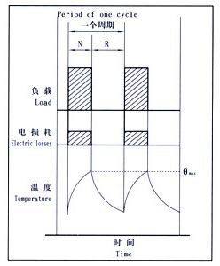
(1)Intermittent periodic work system (S3):
It is a series of identical duty cycles, each cycle includes a period of constant load operation and a period of stop and power-off (see the figure below). In this type, the starting current of each cycle should be free from the temperature rise of the motor. Obvious impact; every 10 minutes is a duty cycle, i.e. six starts per hour

N Operating time under rated conditions
R Stop and de-energize time
Qmax The maximum temperature reached during the working cycle
load duration
CDF=
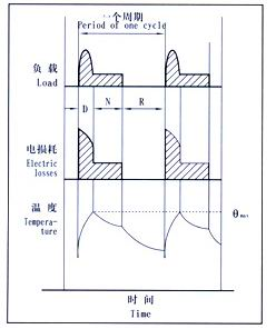
(2)Intermittent periodic duty with start (S4):
It is a series of identical working cycles, each cycle includes a start time, a constant load operation time and a stop and power-off time (see the figure below); the number of starts per hour is divided into 150, 300 and 600 times.

D start time
R Stop and de-energize time
N Operating time under rated conditions
R Stop and de-energize time
Qmax The maximum temperature reached during the working cycle
load duration
CDF=
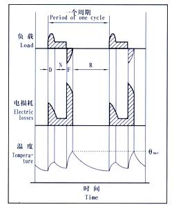
(3)Intermittent periodic duty system with electric braking (S5):
It is a series of identical working cycles, each cycle consists of a start time, a constant load operation time, a fast electric braking time and a stop and power-off time (see the figure below).

D start time
N Operating time under rated conditions
F Electric braking time
R Stop and de-energize time
Qmax The maximum temperature reached during the working cycle
load duration
CDF=
3 When selecting a motor, various starting and braking states need to be converted into equivalent full starts per hour according to the equivalent heat generation. Determine the rating of the motor based on the number of equivalent full starts. Typical examples of conversion are shown in the table below.
Way of working | Braking state | Thermal Equivalent Start Times |
starts per hour | Number of jogs per hour | Brakes per hour | Number of brakes and reverses per hour |
S3 | 6 | 0 | 0 | 0 | 6 |
S3 | 4 | 8 | 0 | 0 |
S3 | 2 | 8 | 2 | 0 |
|
S4 | 150 | 0 | 0 | 0 | 150 |
S4 | 100 | 200 | 0 | 0 |
S5 | 80 | 0 | 80 | 0 |
S5 | 65 | 130 | 65 | 0 |
S5 | 30 | 160 | 30 | 30 |
S4 | 300 | 0 | 0 | 0 | 300 |
S4 | 200 | 400 | 0 | 0 |
S5 | 160 | 0 | 150 | 0 |
S5 | 130 | 160 | 130 | 0 |
S5 | 60 | 320 | 60 | 60 |
S4 | 600 | 0 | 0 | 0 | 600 |
S4 | 400 | 800 | 0 | 0 |
S5 | 260 | 0 | 320 | 0 |
S5 | 260 | 520 | 260 | 0 |
S3 | 120 | 640 | 120 | 120 |
Conversion method: Four times of jogging (the final speed does not exceed 25% of the rated speed) is equivalent to one full start; one electric brake (braking to 1/3 of the rated speed) is equivalent to 0.8 full starts.
4、The basic working mode of the motor is S3-40%, and the technical data of the motor under each working system are shown in the table below. The data on the nameplate of the motor is generally provided according to the reference working system. If the user has special requirements, the data will be provided according to the user. When the motor needs to operate in a way other than the S2~S5 working system, it is necessary to negotiate with our company.
The working mode and technical data of YZR series motors:


The structure of the motor: Insulation class: divided into F class and H class. Class F is suitable for general places where the temperature of the cooling medium does not exceed 40℃; Class H is suitable for metallurgical places where the temperature of the cooling medium does not exceed 60℃. The two motors have the same electrical performance. Protection grade: IP54 for metallurgy; IP44 for lifting. Cooling method: 112-132 is natural cooling (IC0041), 160-355 is self-fan cooling (IC0141), 400 is cooling with internal circulation ventilation and external fan (IC0151). Installation structure type: see the table below
Installation and installation form | code | Available bases | shaft extension |

| 1M1001 | 112~160 | Cylindrical shaft extension at one end |
1M1003 | 180~400 | Conical shaft extension at one end |

| 1M1002 | 112~160 | Cylindrical shaft extension at both ends |
1M1004 | 180~400 | Conical shaft extension at both ends |

| 1M3001 | 112~160 | Cylindrical shaft extension at one end |
1M3003 | 180~315 | Conical shaft extension at one end |

| 1M3011 | 112~160 | Cylindrical shaft extension at one end |
1M3013 | 180~315 | Conical shaft extension at one end |
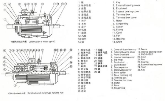
The shaft extension of the motor can be manufactured according to the size or requirement proposed by the user. Transmission mode: The motor is driven by a coupling or a spur gear. If a spur gear is used, the minimum diameter of the pitch circle of the gear should not be less than twice the diameter of the shaft extension. The motor stator outlet box is located on the top of the motor, and the wires can be outlet along both sides of the motor, and the rotor can be outlet from both sides of the end cover. Motor parts name: as shown below

Installation and Dimensions:
1 YZR series installation and external dimensions:
(1) YZR series IM1001, IM1003, IM1002, IM1004 horizontal installation, base with feet, no flange on the end cover motor


(2) YZR series IM3001, IM3003, IM3011, IM3013 motors with vertical installation, frame without feet and flange on end cover、


2 YZ series installation and external dimensions:
(1) YZ series IM1001, IM1003, IM1002, IM1004 horizontal installation, base with feet, no flange on the end cover motor


(2) YZ series IM3001, IM3003, IM3011, IM3013 motors with vertical installation, frame without feet and flange on end cover


